Broadmeadow Estuary Bridge: Integration of Design and
Construction.
Client: Bam Nuttall Ltd
Value: £3,625,000.00
Works Package:
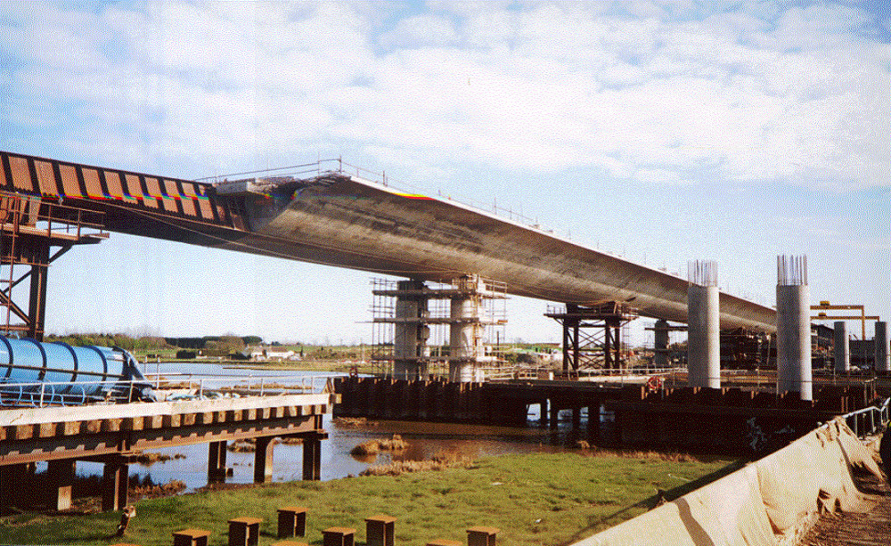
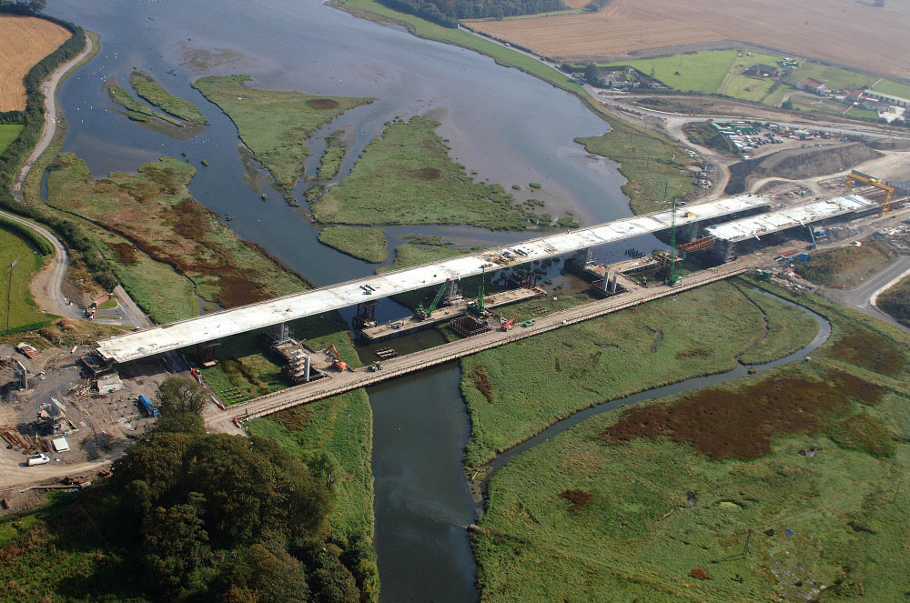
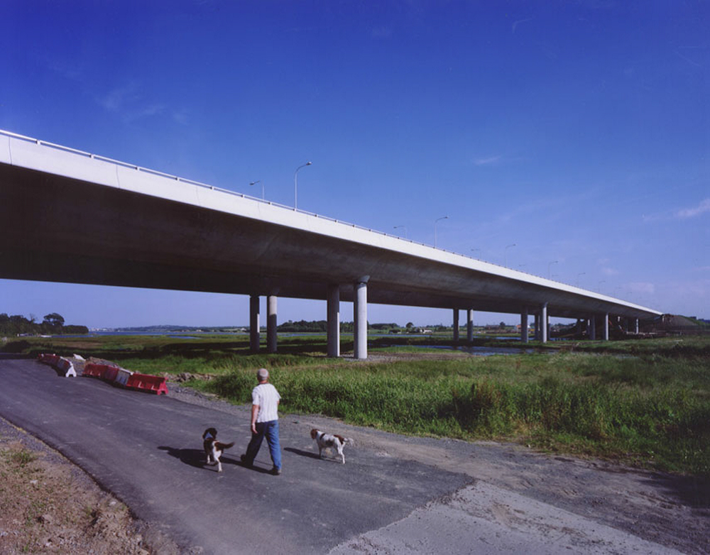
Construction of two side by side viaduct bridges 313m in length.
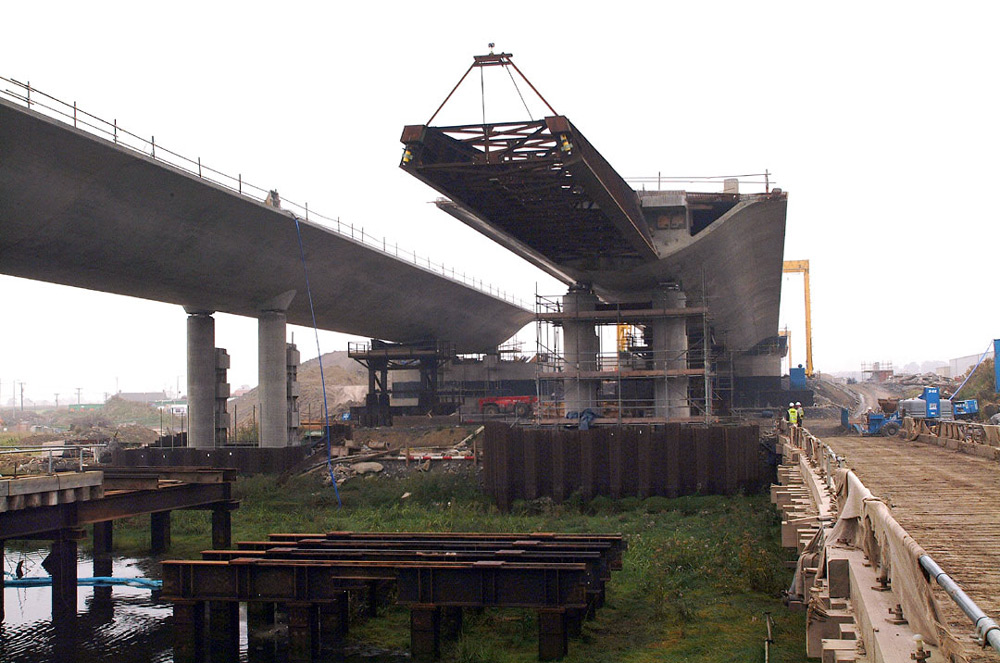
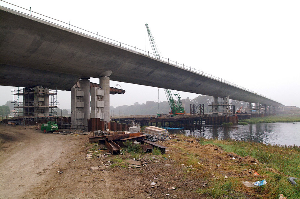
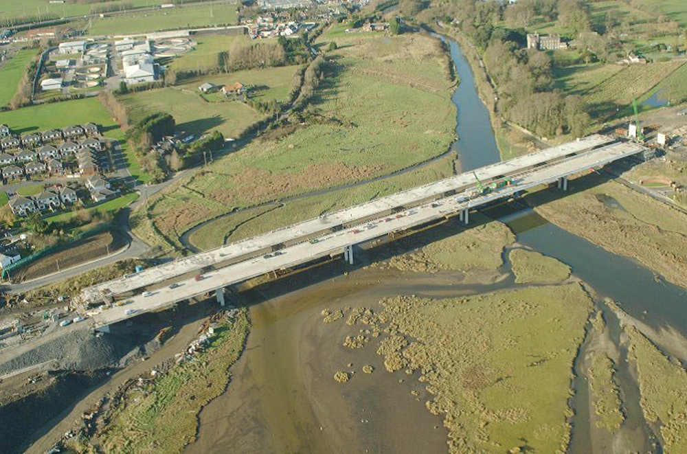
Construction of Piers and Abutments. The main piers were constructed in the river estuary within temporary cofferdams, founded on steel piles and accessed during construction using a temporary bridge.
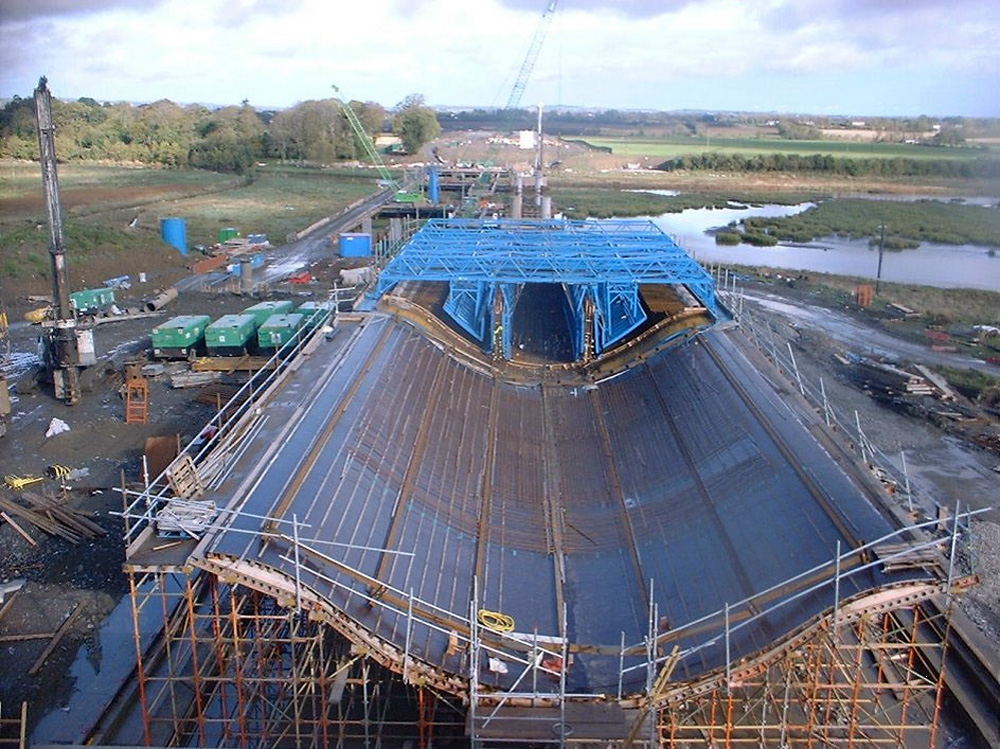
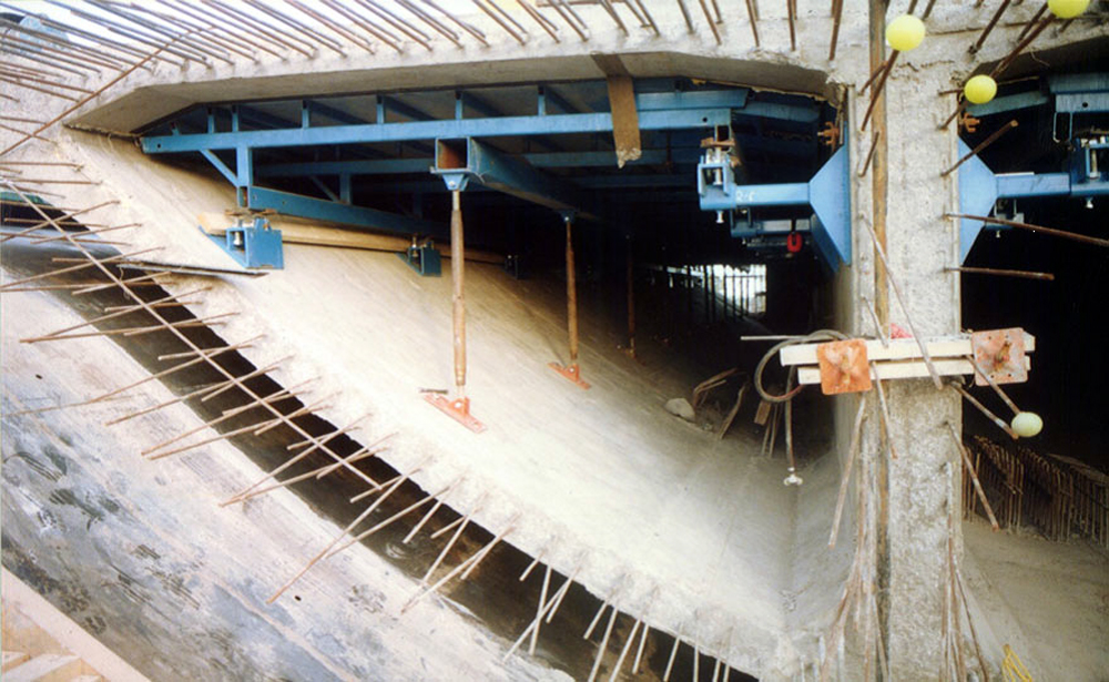
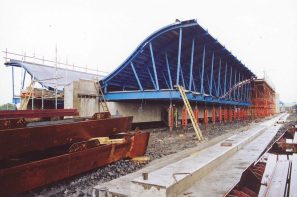
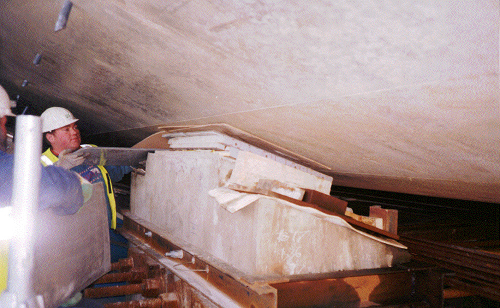
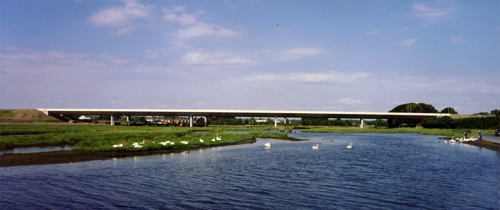
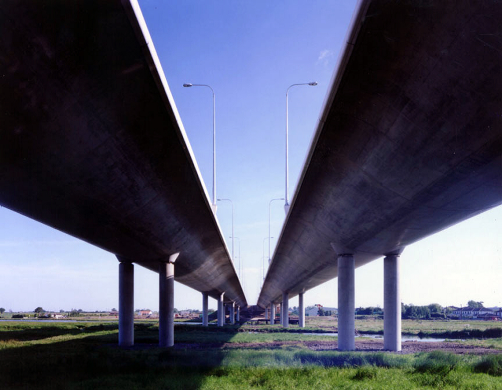
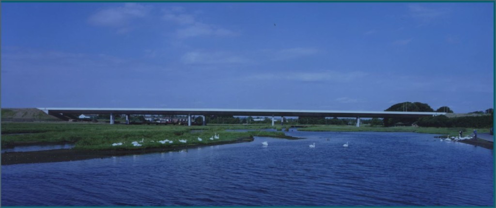
Each bridge consists of five spans varying from 52m to 69m. The bridge superstructure comprised of a triple cell pre-stressed concrete box girder, supported on reinforced concrete piers and abutments at each end. The box girder is 3.20m deep and has a unique curved soffit, designed to mitigate the visual impact of the completed structure as well as minimise external environmental damage. The superstructure for both bridges has been designed to allow construction within the on-site casting yard with the first segment of 21.90m and typical segments of 23m. A multi-staged casting bed with travelling cranes, rebar fabrication, suspended re-usable formwork and long0line assembly techniques to produce the complex deck shapes economically and consistent quality. The concrete segments were cast on specially designed retractable curved steel formwork. The gull-wing shaped forms were supported on temporary falsework set on hydraulic jacks capable of being lowered 450mm vertically once the segment overhead had reached, typically, its two day strength. That space allowed the insertion of the horizontal jack attachments necessary to slide the segments across low friction PTFE pads over the support points. This operation was an engineering feat in its own right.
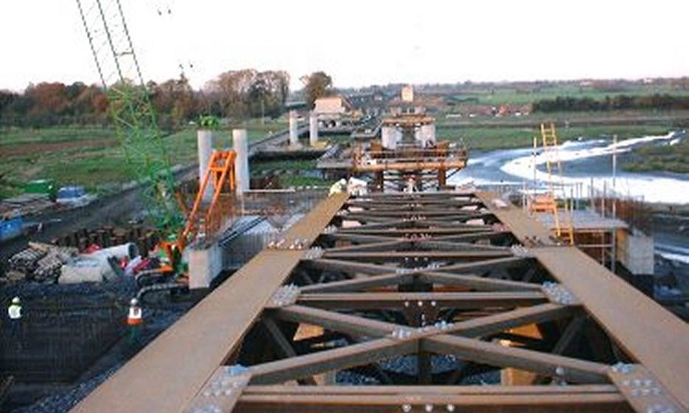
After casting each bridge section was launched as a reinforced concrete structure without intermediate pre-stressing.
Quantities:
- 10,400.00 cu m concrete
- 1,450.00 tn reinforcement
- 105 tn stainless steel reinforcement
Abutments
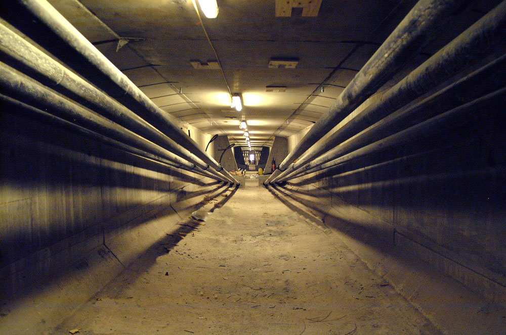
The abutments are simple RC structures placed on CIP bored piles. The main feature of the abutments is the provision of end inspection galleries surrounding the deck ends. These house the supporting mechanical bearing, the expansion joints and the post-tensioning end anchors. Easy access is also available for entry to the internal deck voids via security doors placed in the median sidewalls. Grade 50 concrete was used throughout for durability.
Bridge Deck
- The deck is a uniform depth three cell voided concrete girder with a transversely curved soffit extending between the deck parapets. The cross-section of each deck as designed is 14.7m wide in plan and is shown in Figs 3 and 9, comprising the following elements:
200mm minimum transverse RC top slab spanning between longitudinal webs;
- 2 Nr 2.8m deep longitudinal web beams positioned vertically over the line of the permanent bearings/pier stems. The webs vary in width from 400mm at mid-span widening to 900mm at the pier positions;
10
- 250/350mm varying thickness RC soffit slab taking a curved profile in cross-section resembling a boat shape. The soffit slab connects each edge of the deck top slab with the underside of the webs with a double reverse curve symmetrical about the deck centerline;
- The two side cells are outboard of the webs and are roughly triangular in section;
- The single longitudinal centre cell is in-board of the webs and is rectangular in shape albeit with a concave downward bottom slab;
- Internal bonded tendons;
- 1.5m wide RC transverse diaphragm beams connect the deck structurally across the pierhead lines yielding a 3.2m depth along the centreline and 300mm at the deck edge;
Figure 9: Curved Soffit Deck Section
The deck was designed to take account of the assumed insitu balanced cantilever deck construction process adopted in the Arup Preliminary Report of Jan 1999 proposed as a means of minimising habitat loss within the estuary marsh and mudflats.
The as tendered deck design is post-tensioned longitudinally in conformance with the Class 1 (Combination 1) structure requirements in BS 5400 Part 4, for internally bonded tendons assumed to be protected by web concrete. HA and HB traffic loading was taken from BD37/88 for the assumed lane positions with separate load cases for the future three lane situation. The analysis assumed linear elastic behaviour based on gross section properties, and the analysis was done using the Arup in-house BRILLO 2-D software package. The analyses incorporated the various stages of the assumed construction sequence, including the assumed segment casting cycle, movement of form travellers, environmental effects, and secondary moments (effects progressively built in to the structure with each stage of deck stitch completion).
The conforming design was based on an asymmetric method of balanced cantilevering. The method assumed temporary props on one side of every permanent pier, acting as a strut or tie depending on the direction of the out of balance forces. The segmental temporary props were braced back to the permanent piers and were required to be stressed together down to the pile caps. The asymmetrical nature of this method minimised the out of balance forces and ensured that the permanent piers incorporating conventional pot bearings are always subject to compression axial forces, without uplift or undue rotation.
The method assumed a typical segment length of 4.6m, which is within the range of the current industry standard for moveable formwork travellers. Due to the curved nature of the deck cross section it was envisaged that the segments would be constructed in two separate pours, a soffit pour with cantilevers followed by a top slab pour. This would ensure satisfactory compaction of the curved soffit sections.
The segments would be progressively stressed back to the previously constructed segments with 12K15 multiple strand tendons with anchors at each segment joint.
11
The design assumed construction effectively from one side of the estuary to the other working outward from each permanent pierhead. Completed balanced cantilever deck sections would be progressively stitched together at midspan using bottom continuity tendons installed to carry the superimposed and transient loads of the permanent situation.